Six caps on the selectivity switch
S2 with old, and new bees...
Click for larger view
The wires leading to the switch were in good condition, allowing replacement without completely removing it. Sometimes old insulation cracks, or wires break. Once the switch was back in place, I started to check the entire area under the chassis. There were a few times when a cut component lead would disappear into the mysterious fray of wire... I was able to find them all with a little help from a bright light and small amounts of compressed air. There were a few solder splashes, mostly from the solder removal process. Other components were inspected for signs of heat stress - color changes, slight bulges, tiny cracks. I randomly measured some resistor values, and they were within tolerance. I had replaced one resistor earlier in the project, as it appeared to have been stressed with heat. Even though it measured within tolerance, such parts should always be replaced.
Almost there...
The Buzz...
There is a mysterious 8-pin socket on the back that will allow power via DC operation. If you have a DC supply with 208 volts at 105 ma, and 6.3 volts at 4.1 amps, you're in business - add your batteries or supply for the perfect 40 pound bundle for your trip to the park. Don't forget to throw in your speaker - the one in the metal enclosure. Enjoy the broadcast of the game with this great portable set...
I replaced the power cord. The original wasn't too bad; however, this is always a good idea considering the age of the components. I should have installed a fuse as well... there is a hole in the chassis, originally intended for an rf connector. I will install one before releasing it from the quarantine of my work area.
Initial power up configuration...
The audio output has a terminal strip for a 3.2 Ω or 600 Ω speaker. I have an impedance matching transformer that was hooked to the 600 Ω terminals, then connected the 8 Ω speaker. A random length of wire was strung across the floor in the basement, much to the delight of the cat.
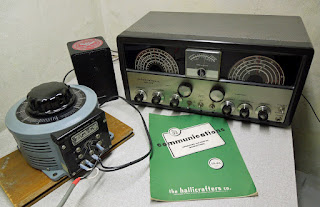
The Powerstat was plugged in, and I looked at the point where the AC output would be near the minimum operating voltage of 105 vac. While the label says acceptable voltages range to 125, I figured that something idle for a few decades would be happier with a lower voltage. The radio was then plugged in to the variable AC supply, and the Fluke meter was attached as well to monitor line voltage as I rolled up the AC.
The manual describes two methods for tuning - also noting that it was calibrated with the bandspread dial fully CCW. I set the main dial near an expected local AM broadcast station. The bandspread was not fully CCW, as I wanted some 'room' to rock the adjustment. Volume and sensitivity controls were set near the low end, and other switches selected the AM broadcast band, and the selectivity at 5kc.
Power up
Leakage current?
Old electronics can be dangerous - I used this Simpson leakage current tester to evaluate the radio's safety. I am going to operate the radio with an isolation transformer, and at a reduced AC line voltage.
It's a keeper. All controls and bands work well. The calibration is off a little - it is close enough for now. I don't have the signal generators to go through the alignment procedure.
Next: I'll post the tiny isolation transformer, voltage step-down project.
Also, a separate blog about past restorations, including an Atwater Kent (a 20 Big Box and a 40), a Crosley Trirdyn, and the Grunow will launch at some point.
Also, a separate blog about past restorations, including an Atwater Kent (a 20 Big Box and a 40), a Crosley Trirdyn, and the Grunow will launch at some point.


