Sunday, March 12, 2023

Let the fun begin....


Emerson BW 231 - 1938

The Half Mae West....


My typical parts-is-parts replacement method

this is one of the easier parts to replace.


Capacitor C7

That's all, kids!


Sunday, February 19, 2023

New Restoration Project - the "1/2 Mae West...." 1938 AM - Short Wave Radio


A recent gift - from a friend familiar with my interest in restoring old radios.

This is an Emerson model BW-231 - also known as the Half Mae West.


Emerson "1/2 Mae West"


What's the frequency Kenneth?


Emerson Logo Detail


A brush with some old-school Rock and Roll


Carl Griffin - Grammy Awards, Motown, a Jazz record label... and much more - 

bought this from Joey Dee - Peppermint Twist - in 1968.


He never played it, as it was in need of restoration. I hope to get it rocking' and rollin'!


It is a good candidate  for restoration - the circuit is a common 6 tube receiver design

that was popular for several decades - schematics and modern replacement electronic parts are available.


First Look Inside....


The primary parts to replace are the old wax, paper, and 'bumble bee' capacitors - the electrolyte

inside the originals disintegrates - turning the capacitor into something that may short,

act as a resistance, and ignite or explode, damaging other componentsthat are NOT

easy to find replacements for - e.g. transformers coils, etc.


Under the hood....


Component density isn't too annoying - this will be relatively easy to get to the parts that need replacement.


Wax caps - the four tubular tan bits....


Not sure what the two little red bits are... will need to figure that out before powering up.

Next step - I will draw diagrams and schematics, recording the values of each of the parts that are removed. There are about ten parts I will order and replace, followed by some more detailed detective work to identify any mysteries as I progress.


Stay tuned in, so to speak.


Tuesday, August 11, 2020

Webcor 2110 Sings Again


She listens, she sings.


A little Art Blakey, for her first full run in decades.


Wednesday, August 5, 2020

Webcor 2110 Parts Replacement and First Light

  
This Webcor 2110 reel to reel deck was an excellent candidate for a relatively easy restoration - it was in good physical condition, and nothing was missing. There was a schematic inside the case, and, of course, the world wide web is your informational friend. http://www.tapeheads.net is a great resource for anything tape related.


After the cleaning and initial evaluation, as in the previous post, I ordered and replaced the paper/wax capacitors, as well as the Bumblebees - see previous post - and one resistor that was obviously heat-stressed.

I like to keep things as 'original' in appearance as possible, although the goal is function - and this stuff is hidden from view. Still, neatness counts ๐Ÿ˜

Component values used in old electronics are often a little different than the modern parts that are typically available. This site has a great selection of parts that match original values - https://www.tubesandmore.com

There are endless, and sometimes ridiculous discussions about capacitor choices for audio circuitry. Search away. There were some component choices that could improve the audio performance.

My take? The heads are worn - I have a decent 'hi-fi' deck - the Revox - see earlier posts - and this thing is a monophonic marvel with a frequency response in the order of 70 - 10Khz - I don't expect it to rival some hi-fi wonder. I plan on recording some vintage shows, so it is fine without extensive mods.

Here are some parts-is-parts images, and the first light-up video.


Three for One! The yellow, gummed-up thing is a multi-section capacitor, with three caps inside. There are modern versions; however, because of the odd combination of values, I will use three separate parts.


Some of the caps are hiding under a mess of other stuff, and can be somewhat annoying to replace. 


The only other type of component replaced was a toasty resistor - the middle of the body had been cooked - the three bands should be yellow, violet, and red - and measuring the value shows that it is way off - compared to...


...this value, which is correct.


It's ready to fire up. Ideally, I'd ramp up the voltage with a variac - 70-something year old components can be a bit unpredictable ๐Ÿ”ฅ๐Ÿงฏ๐Ÿงจ   ๐Ÿ˜œ


First function check....


Play and record, both directions, FF and REW, and the eye tube work. I still need to get some felt on the tape head pressure arms - cotton balls used to protect the forward and reverse play heads - and see if it actually handles the tape properly, and records and plays back. The heads were quite nasty looking!


Next: The reel (so to speak) test!

Thursday, July 9, 2020

Webcor - Initial Electrical Evaluation


I've finished an initial cleaning of the upper mechanical tape transport circus, so I'm moving on to the electrical bits. Once the electrical bits have been revived, I'll return to the motors, springs, and levers for adjustment.

Vintage electronics, in this case from 1952, have components that don't age well - powering them up after decades of storage is not a good idea!

There are 13 wax-covered capacitors that must be replaced, as they no longer work as intended - they often can turn into resistors, short out, or have radically different values. This can cause extensive damage to other components, including fire, and shock hazards! 
๐Ÿš’๐Ÿงจ๐ŸŽ†๐Ÿงฏ๐Ÿ’ฃ
Don't plug these things in until a thorough evaluation and replacement have been done. There are also several old Bumble Bee capacitors - they have black bodies with a number of color coded stripes - these must be replaced as well. Other components will be checked for any signs of heat stress, cracking, or bulging.


Some of the wax paper capacitors that will be replaced....


All of the capacitors and sketchy looking parts will be located on the schematic, which was found inside the case. Then, an initial parts order will be made.


Sometimes, manufacturing changes will vary from a supplied schematic. Component values may change, parts deleted, or additional parts may appear ๐Ÿ˜ƒ

I have worked on gear that people have 'modified' - deleting or improperly replacing parts with things that are ridiculously dangerous ๐Ÿ’€, pointless, and some that don't do anything at all! ๐Ÿ˜‚

Here's my typical secret process - been doing this for a few decades ๐Ÿค“

Usually, I like to concentrate on one type of component. In this case, the capacitors. I chose the easiest one to start with ๐Ÿ˜œ


This is an example of a wax paper multi-section capacitor - C14A, 14B, and 14C, three caps in one package. There are four leads - one that is common to all three sections, and then seperate leads for section A, B, and C. The color code and values are listed on the cap - sometimes hard to read, although easy enough to compare to the schematic for verification.


The highlighted areas show how each section is wired into the circuit. It is important to note that the actual wiring isn't as always straight forward as the neat schematic would suggest. In this case, wires from 14A and 14C both connect to the socket for the 6X5 tube - only 14A is actually part of that tube circuit ๐Ÿ˜„
It is common for tubes to have unused pins - so in this case, the wire for 14C goes to 6X5's unused pin 4, where the two resistors are tied - see the red circle above. This is a common trick to ease wiring and keep leads short - avoiding unwanted effects that may be caused by long leads.

The circled component is resistor R27 - with a value of 4700 โ„ฆ, 1Watt. Take a close look....


This is tied directly to capacitor 14C. Note the very dark color of the middle part - the body should be brown, like the top end. The value is indicated by the color bands - which should be, from the bottom, yellow, violet, and red. Without a schematic, you'd have to guess the value, as the red band is charred. The top silver band indicates a value tolerance of 10%. This resistor and cap are part of the rectifier tube circuit, which supplies the power to the whole mess - and over time, this part was getting baked - possibly due to the filter cap leaking and on the way to failure, or something 'downstream' has failed, and drawing more current than normal. To be determined ๐Ÿ˜

And finally, something a bit silly to finish....


The resistor issue is easy to explain... the frog, not so much.

Now, off to creating the initial parts order - there is always some component that is overlooked ๐Ÿ™„

Next post, typical soldering procedure for C14 - A, B, and C ๐Ÿ˜„


Monday, June 29, 2020

Webcor Reel Table


Before digging into the electrical restoration, I'm going to work on the mechanics on the top.

This is due, in part, to a minor annoyance - the chassis is 'locked' inside of the case.
The prongs for the AC power cord protrude into an opening in the case. The entire unit drops into the case and is a tight fit, without wiggle room to tilt, tip, cajole, or otherwise position such that it will simply lift out. ๐Ÿ™„

There is a narrow access panel on the bottom, so that the tubes can be replaced.
To get the silly thing out, I bent the external tabs of a little protective box inside. Then, I drilled the rivets so that I could retract the silly thing.

To review, note the fit ๐Ÿ˜


The dangerous electrical bits reside below ๐Ÿ”Œ


Get Bent


Zap!


Although that annoyance has been solved, I still want to work on the top, before extracting the silly thing.

That brings us to an amusing carnival of wheels, levers, springs, washers, and miscellaneous oddities. Refer to the first image of the top of the deck ๐Ÿ˜Ž. Sometimes, there will be service manuals with parts diagrams, etc. I haven't found one for this, although a more extensive search in the Tapeheads.net forums may help. I'll simply document part placement with photos.

There are two of these reel tables. Since they are relatively unencumbered with multiple springs and interlocking mechanisms, they are easy to disassemble.

Without a parts diagram, make sure you can reassemble things - take a photo, make a drawing....


Get Reel, so to speak....


Parts is Parts


There are varieties of bronze alloys used for bushings - some require lubrication, others are self-lubricating. If it is of the self-lubricating type, I'll simply clean all of the parts and reassemble. There is a simple friction clutch - the spring, felt pad, and washers - and a rubber tire that drives the reel table. Although not easy to see in the photo, parts of the clutch have little index tabs that require proper orientation. In this case it's easy to figure out if the whole mess ends up in a pile - in some cases, it's not so obvious, so take note ๐Ÿค“

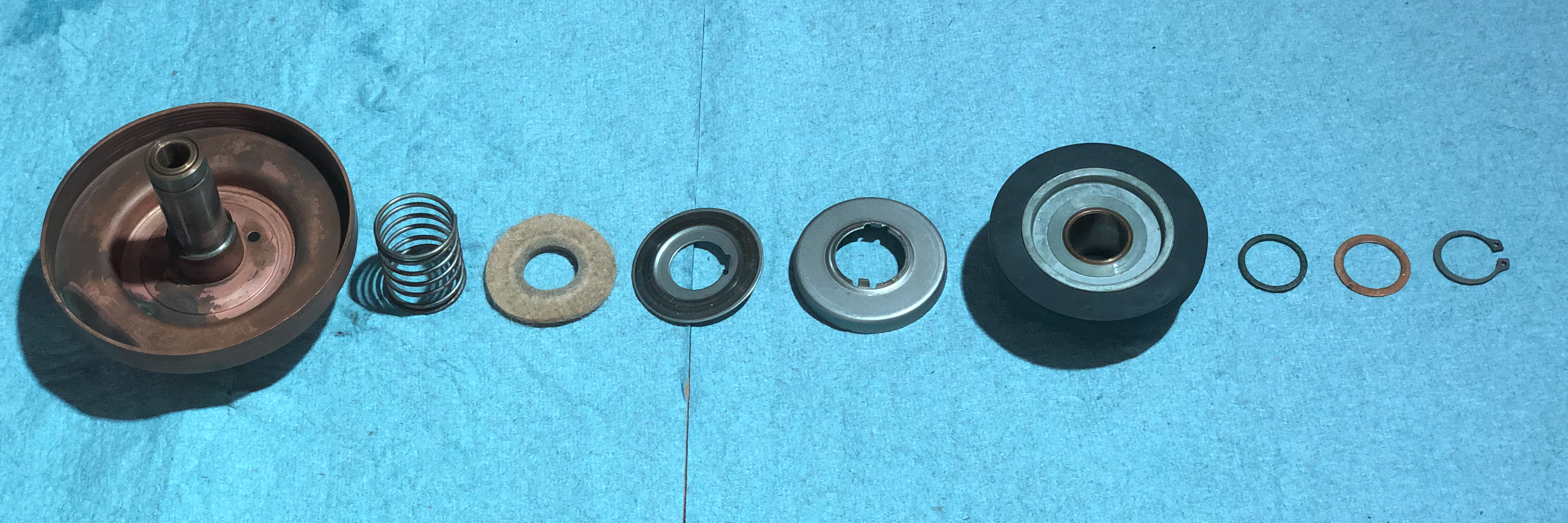
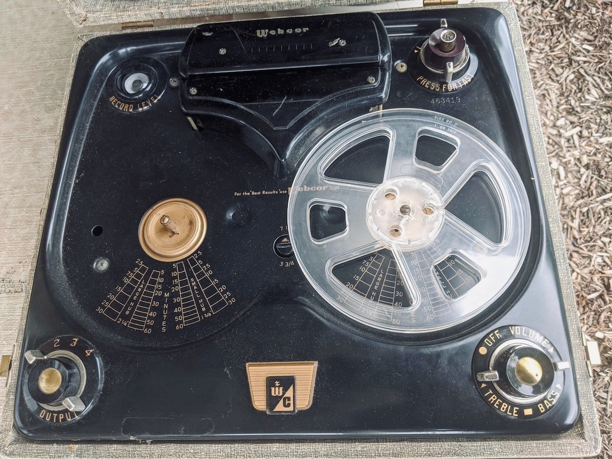
Next: Digging further into the reel table drive mechanics.


Wednesday, June 10, 2020

Webcor 2110 Reel to Reel Restoration


This Webcor 2110, ca. 1952, found its way into my collection of anachronistic, incredibly useful toys.


Oh Joy!


Moving parts are always more amusing for sound playback toys


This deck records and plays a monophonic signal in both directions - when the tape is near the end of the reel, you turn a knob to reverse the direction of the tape "...without bothersome reel turnover." ๐Ÿ˜ƒ
There are two tape speeds - 3 1/4 and 7 1/2 inches per second. On a 7 inch reel, you can get a delightful 2 hour recording ๐Ÿ˜… with an astonishing frequency response up to 10khz, with less than .5% wow and flutter.  Original price, in 1952, was $207.50.


Detail of the high-tech tape time counter


Beautiful mic - still works


These images are from an initial evaluation. It has all of the tubes, and is mechanically complete. Subsequent posts will go into more detail about the mechanical restoration for each section, followed by the electrical work.


First look under the cover...


Closeup, along the tape path by the heads. One head is in contact with the tape, and they alternate with tape direction. Eventually, I'll post little videos about the very unique mechanisms.


Head wear and oxide buildup. Always have dice on hand as little repair positioning aids ๐Ÿ˜„


Inside the head case (so to speak)


Missing some of the felt pressure pads. These gently press against the tape for good tape-to-head contact.


Schematic


The tubes are common if they are needed. The tricky part is whether the worn heads still work - aside from wear, sometimes a fine wire inside the head assembly will break. Heads are very rare. If they are shot, this still makes a great little guitar amp, for that sweet tube sound.

Next: Cleaning the topside mechanics.